How Light blocking Sensors Work??
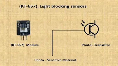
A light blocking sensor consists of an IR transmitter and a phototransistor receiver .phototransistor works similarly to a normal transistor
except it uses light-sensitive material at its base.
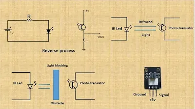
Normally when we applied voltage to an LED, the LED glows now we
can reverse this theory by using photo-sensitive
material, when we emit light on this sensitive material it generates voltage.
The light which is emitted by the IR transmitter is not visible
to us as it is infrared light.
How do light blocking sensors work??
IR Led transmits an invisible light signal to the photo-transistor located at the receiving end. When light hits the base of the transistor it generates voltage until and unless there is no obstacle. When an obstacle is introduced between the IR transmitter and photo receiver then no light reaches the receiver. Hence no voltage is generated. Normally the output of this module is LOW when there is an interruption of light, so no light reaches the transistor and output goes high. This type of sensor has wide application in counting machines, RPM measurements, and security systems.
Parts Required
- KT-657 (light blocking sensor module)
- Arduino
- Jumper wires
- LED
- Breadboard
Schematic Diagram
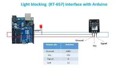
Connect the ground pin of the light blocking sensor to the ground pin of Arduino, the VCC pin to 5v, and the Signal pin to 8. Also, connect the positive lead of LED to Arduino pin 11.
Code -
int sensorpin=8;
int sensorvalue;
void setup()
{
pinMode(ledpin,OUTPUT);
pinMode(sensorpin,INPUT);
Serial.begin(115200);
}
void loop()
{
sensorvalue = digitalRead(sensorpin);
if (sensorvalue==HIGH)
{
digitalWrite(ledpin,HIGH);
Serial.println("light blocked");
}
else
{
digitalWrite(ledpin,LOW);
Serial.println("no blocking");
}
delay(20);
}
First, initialize pins of sensors & LED and variables. We have declared a variable name sensor value to read values from sensors. In void setup, we configure pins as INPUT or OUTPUT. We want to read values from the sensor pin so we will declare it as INPUT. Also, we configure the baud rate to 115200.
In the void loop, we continuously read values from the light blocking sensor and store values in variable name sensor value and we check here condition if it is HIGH or not. HIGH means there is an obstacle present. If there is an obstacle then light emitted from IR led does not reach the phototransistor and the sensor sends a HIGH signal to our Arduino which we printed as “light blocked”. Here we have written code to turn ON led when the light is blocked
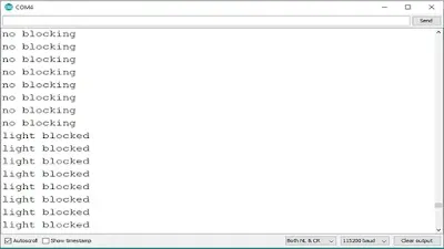
When there is no obstacle the light emitted from IR led reaches the phototransistor and the sensor sends a LOW signal to Arduino which is printed as “no blocking“ and the LED connected to pin 11 will turn OFF. We have introduced a delay of 20 milliseconds.
Output -
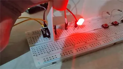
You can see output on the Serial monitor. When we add an obstacle then the output will be “light blocked” and when there is no obstacle then the output will be “no blocking”.
Conclusion -
Today we learn about light blocking the sensor, how to use light blocking sensor with Arduino, and how light blocking sensor works.
"I hope you find this IoT blog very helpful to you. In the upcoming lesson, we will see more about IoT sensors till then bye. See you all in my next blog."

